
How does your hard drive work?
There are really only two sizes of hard drives.
The laptop 2.5" hard drive (shown at the left)
The desktop 3.5" hard drive (shown at the right)
Note: The numbers above are the diameter of the disk inside the drive. The 2.5" laptop drive is actually 2.75" wide and the 3.5" desktop drive is actually 4" wide.
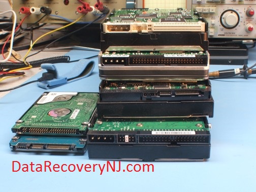
They may have different interface connectors but they are all basically the same drive. If you open up your external USB2 or Firewire case, iPod, TiVo, Apple, PC, Laptop etc. you will find one of these drives.
Today there are only 5 manufacturers of hard drives:
Seagate / Maxtor
Western Digital
Hitachi / IBM
Toshiba/Fujitsu
Samsung
Sorry, Dell, Apple, Compaq, Gateway, LaCie etc. do not make hard drives. They buy their drives from one of the manufacturers above and put their name on it.
Assembly
There are two main systems in the hard drive.
The Electrical system.
The Mechanical system.
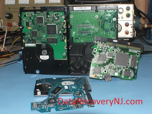
The Mechanical is the black aluminum case in the picture above.
The Electrical is the blue or green Printed Circuit Board (PCB) sometimes called Printed Wiring Board (PWB) or Controller Card shown in the picture above.
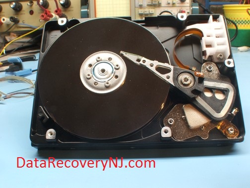
The Mechanical part is enclosed in a sealed case. The case is sealed to keep dust out. One single speck of dust can destroy your drive. This case should never be opened!!! (More on this later).
The Mechanical part looks simple. There are only two moving parts. The disk (also called the platter) which spins around 7,200RPM and the actuator arm which rotates only a few degrees back and forth (much like the arm of an old record player).
A hard drive has at least one platter and could have up to ten platters. Each platter will have at least one head on the top surface and one head on the bottom surface of each platter.
Notice that the top head is defective in the above picture and has lifted off the disk surface.
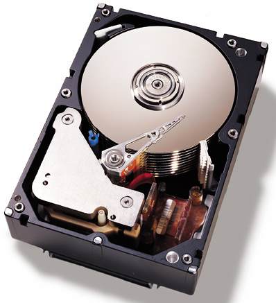
Note: The white part to the right of the actuator arm is the "parking" area. This is where the heads go when the drive is not spinning.
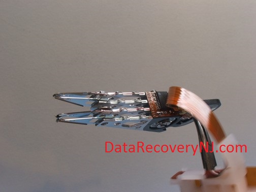
The heads are spring loaded together and move together as one unit.
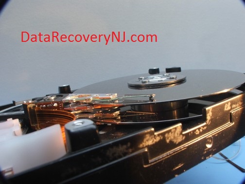
Above you can see the black preamplifier chip which which increases the signal from the head. The tan ribbon cable transmits the signal from the head to the main controller card (mounted outside the drive). Power for the actuator arm "voice coil" is also supplied through this cable. The actuator arm moves by the same principal that drives a audio speaker (A fixed magnet and a movable "voice coil").
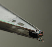
Both the head and disk surface have a highly polished mirror finish. If you ever played with two highly polished steel blocks you will notice that they stick together and are hard to pull apart. That is exactly what will happen if the head ever came in contact with the stationary disk surface. Now if you take the same two polished steel blocks and slide them relative to each other you will notice that they slide quite easily, in fact if you had a large mirror surface you can slide the mirror block along the surface much like an air hockey table. The block rides on a cushion of air so small that dust particles can jam between the gap. This is exactly how the head rides on the disk surface. A dust particle to the head of your hard drive will have about the same effect as a 18" rock would have on you car if you drove over it at 60 MPH.
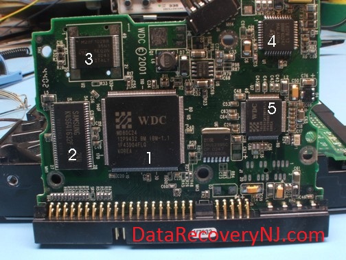
All hard drives have a controller card also known as PCB (Printed Circuit Board) or PWB (Printed Wiring Board). The controller card contains a complete micro computer system. It contains a:
1. Microprocessor
2. RAM (Random Access Memory)
3. FLASH Memory (Memory chip that does not forget code when power off)
4. Servo Controller chip (powers the platter drive motor)
5. Actuator arm driver chip.
When power is applied to a hard drive its microprocessor loads "boot" code from the flash memory and internal memory to the RAM chip. This code is just enough to spin the drive up to speed and start reading data off the disk surface. The disk is broken up into "tracks" or "cylinders" . Tracks are cylindrical rings of magnetized particles on the disk surface. A disk can have several thousand of these rings. These tracks (rings) are numbered from negative 20 and up to several thousand with negative 20 being the closest track to the center of the disk. Tracks negative one through negative 20 are used exclusively by the hard drive. This is called the "service area". This is where the hard drives main operating system is stored. Also stored in this area is a translator table (which tells the drive where the tracks are) and The "P-List & G-List" which is a list of the bad sectors on the drive. This information is unique to each and every drive. Tracks zero and and above is called the "user area" this is where all your data goes when it is saved to the hard drive. Only the hard drive can access the service area. You computer can only access the "user area".
Typical boot process.
1. Computer is turned on.
2. Hard drive micro controller executes internal boot code.
3. Code is copied from Flash Memory and executed in RAM.
4. Drive is spun to speed and stabilized.
5. Actuator arm is moved from parking area to service area.
6. Code and other parameters are loaded from service area
to RAM.
7. Several self tests are run.
8. Communication is started between the hard drive and your motherboard.
9. Your BIOS detects the hard drive.
10. Your computer loads it's operating system from user area of the drive.
Note:
If anything goes wrong in steps 2 through 7 then steps 8 through 10 never occur.
If your drive's self tests fail, there is no communication between the hard drive and your motherboard. It is the same as if you unplugged the cable between your drive and motherboard.
There are hundreds of software programs that claim that they will recover data from your hard drive. What they don't tell you is if your drive does not reach a ready state, their software is totally useless.
There are hundreds of things that could go wrong with your drive which will prevent it from reaching a ready state. If any single one of the little components on the PCB burn out, your drive does not become ready
Sometimes the firmware in the flash memory becomes corrupted.
Sometimes the firmware in the service area becomes corrupted.
One wrong bit will prevent your drive from going to a ready state.
We can diagnose and repair burt out components on your PCB. We even have special machines (like they use in the factory) that can debug and reload the firmware on your drive.
Call Data Recovery New Jersey
Toll Free 888-548-9399
Talk directly to an engineer
Data Recovery NJ
12 New Providence Road
Watchung, NJ 07069
Click Here for a free estimate
e-mail us: info@datarecoverynj.com

To pay your bill by Credit Card:
1. Enter the amount in the box below.
2. Click the "Pay Now" button. Data Recovery NJ
Promote Your Page Too

